The Swirl Flames Data Repository
Geometry
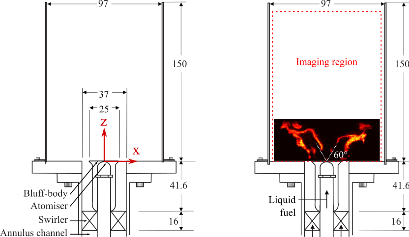
The Cambridge bluff-body swirl burner consists of a burner base with a Db = 25 mm conical bluff-body and a D = 37 mm annulus with a swirler upstream. Four quartz plates are supported by the burner body, forming a square enclosure 97 mm wide and 150 mm tall. The outlet is open to the atmosphere. Two schematics are given below. On the left, please note the burner axes defined at the fuel injection point in the centre of the bluff-body. These axes will be consistently used throughout the downloadable data. On the right, the imaging region is highlighted in red. All dimensions are in mm.

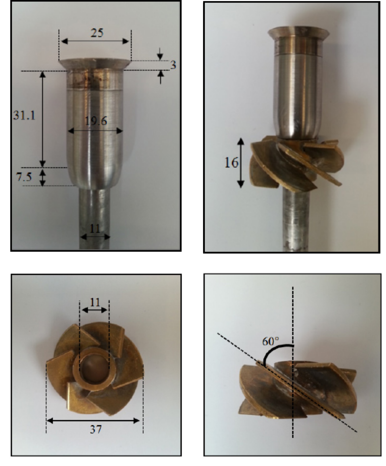
The geometric swirler upstream of the bluff-body consists of six vanes at 60° with respect to the flow axis. The direction of the air swirl was clockwise when looking at the nozzle from the combustion region. Images of the swirler and bluff-body are given below. All dimensions are given in mm.

Credit: [Cavaliere PhD Thesis]
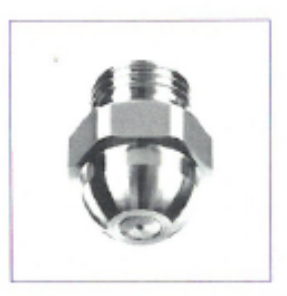
Air enters the combustor at atmospheric temperature and pressure through the swirled annulus channel around the bluff-body. Liquid fuel is injected in the centre of the bluff-body with a hollow-cone pressure atomiser (Lechler model 212/220), shown below.

Lechler 212/220 series hollow cone atomiser
Geometry files are downloadable below.
| Geometry | File | Author | Contact |
|---|---|---|---|
| Swirler | Swirler_geometry.tin | Dr Huangwei Zhang (hz283) | Dr Andrea Giusti (ag813) |

